
Max Le Moine
Industrial Designer
Wreck Zone
Table Top Basketball Game
4rth Year, 2 Months
For my minor, fourth-year studio, I was given the task of designing and building a game for a Wreck Room. Due to experience, my team (Behzad Rashidi, Farah Alnabiti, Patrice Temush) and I wanted to re-design a table-top Basketball Game that Behzad previously played. Building our product was a great opportunity for my to enhance my teamwork and model-making skills.
Initial Design
Ideation
To kick off the project, group members each prepared a design report to gather information (below) on existing products. Other than research, the team also prepared concept sketches (shown to the right). Theses were then compiled into group concepts.
Who: Kids/teens, competitive people, with friends, Parents (buying product)
What: shoot ball into hoop with different levers
Where: house, living room, wreck room
When: weekends, parties, have friends
Why: have fun, compete, relax
Opportunities: aesthetics, Replace plastic cover, make self-standing

Preliminary Execution
CAD Assembly
As our product consisted of more than 20 parts, it was crucial to model and assemble them in CAD before the product was manufactured. All team mates worked together to great the individual parts which were assembled by Behzad using a bottom-up process while creating supporting parts. This allowed us to ensure/edit the parts fit together. Part files were shared back and forth using Google Drive.


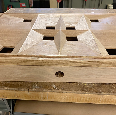
Game Board
The most important part of the model was the game board which was CNCed out of wood. We originally wanted to do this out of 1 piece of wood. However, One we met with our CNC technician (Marta from the Wood Source) we decided to just CNC the top a glue on the sides to avoid double-sided machining (added costs). Patrice used CAD modeling to program the CNC machine. Post-production operations were made to finished the part.
Buttons
The Buttons were designed in CAD and manufactured using 3D printing. A double-nozzle printer was used too make the number a different colour (black or white) than the rest of the buttons. This took several test prints.


Cover
An Acrylic sheet was sourced and used for the cover. This was designed in CAD to ensure it fits the board’s tolerances using SOLIDWORKS. The sheets were then cut and glued together. Screws and groves were used to mount the cover to the game board.
Hammers
The hammers were designed around the existing parts and then edited to fit the needs of the new product. We decided to laser cut the hammer arms and 3D print the hemmer ends. Once the dimensions were confirmed in CAD, Adobe Illustrator was used to create a die line and positioning diagram.


Decals
Decals were used to mark the holes and tie them to each button. These were designed using Adobe Illustrator and cut on a Vinyl Cutter. Other graphics were designed around the 4-digit displays.
Electronics
In order to keep time and scores, Behzad designed a computer program and electronics for the product. He also designed the backboard/net to go with the electronics. The program was coded using Micro Python for a Raspberry Pi Pico with the assistance of AI technology. Electronic components in the subassembly include:
-
IR Motion Sensors x2
-
4-digit Segmented Display x4
-
Buzzer x2
-
Push button x1
-
Raspberry Pi Pico x1
-
Breakout board with screw terminals x1
-
10-Pin Flat Ribbon Cables x2
-
USB -A to Micro USB cable x1
-
Rechargeable Powerbank x1

Assembly
Game Board Casing
To frame/hide the mechanical and electronic components, Patrice built a casing to be attached to the main game board. Using offcuts and similar Maple wood, work (sanding and careful joining) was done to seamlessly incorporate this piece with the Game Board. This also included a MDF board fr the game reset bottom.

Hammer Supports
Supports were 3D printed for the hammers to ensure they work properly. As there are many supports that need to be placed in specific locations, a diagram was made from the CAD assembly. The diagram was used to drill holes in an MDF board that holds the supports and is attached to the bottom of the casing.
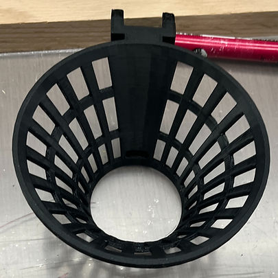
Nets and Backboards
The net assembly was designed in CAD and 3D printed to fit the IR sensors. The backboards were Laser cut with acrylic to fit the displays and decals. These were assembled using only 1 screw.
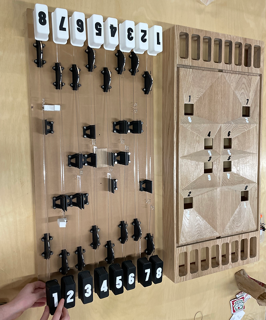
All Together
After everything was ready to go. We assembled the cover, game board, nets/backboards, and supports together. IKEA legs were added to make the product free-standing.
Final Model

